")
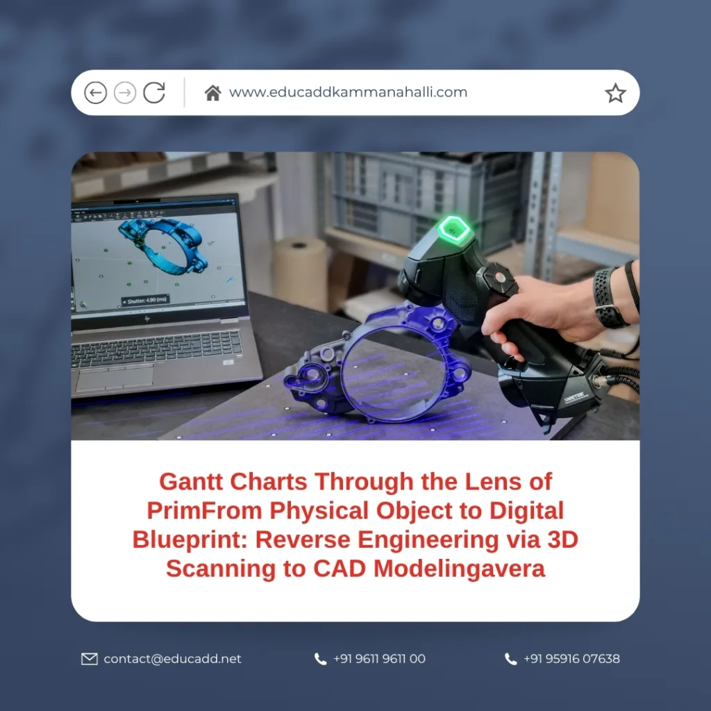
From Physical Object to Digital Blueprint: Reverse Engineering via 3D Scanning to CAD Modeling
In a world driven by digital design, converting a physical object into a parametric 3D Scanning CAD Modeling is a powerful skill. The process of reverse engineering—from 3D scanning to CAD modeling—lets you recreate, analyze, or improve existing parts even when original design files are unavailable. This post guides you through the end-to-end workflow, highlights practical tips, and shows how you can overcome common challenges. Whether you aspire to restore a legacy component or build a prototype that must fit with existing hardware, this technique bridges the gap between real and digital.
3D Scanning CAD Modeling
Here’s what we’ll cover:
-
Foundations and Preparation
-
Data Capture: Choosing and Executing 3D Scans
-
Processing & Mesh Optimization
-
From Mesh to CAD: Modeling Strategies
-
Validation, Iteration & Best Practices
Let’s dive in.
1. Foundations and Preparation
Before you fire up the scanner, you must set yourself up for success. A solid foundation makes the rest of the workflow smoother.
Why reverse engineering matters
Reverse engineering enables you to recreate geometry when original CAD data is lost or inaccessible. It allows you to inspect, refurbish, or adapt parts without starting from scratch. In industries like aerospace, automotive, and heritage preservation, you often need to digitize real-world parts into editable CAD models. This process empowers design modifications, quality control, and integration with modern manufacturing pipelines.
Moreover, when you proceed via 3D scanning to CAD modeling, you turn a physical asset into a parametric representation that supports further modifications, simulation, or manufacturing.
Key concepts to grasp
-
Point cloud: a collection of discrete 3D points captured by the scanner.
-
Mesh (triangular mesh / STL): a network of triangles representing surfaces.
-
Parametric CAD model: a boundary representation (B-Rep) with features (extrudes, lofts, fillets) that you can edit.
-
Design intent: the logical reasoning behind features (why a hole is at that position, which faces should remain flat, etc.).
-
Datum / reference geometry: planes, axes, or features used as alignment anchors.
You must always respect design intent, because simply creating a faceted model from scan data fails to capture the true functional relationships.
Planning and part preparation
First, inspect your physical object. Clean it; remove dust, grease, or rust. Mask reflective or shiny surfaces (sprays, powders, mats) as needed to improve scanning quality. Identify key features (holes, flats, symmetry) that you must preserve. If possible, apply reference markers to help align scans.
Decide the coordinate system you will use: which face will be the “front,” which edges define axes. Label or align datum features early so that downstream modeling is consistent.
Also, choose your scanning strategy (single full scan, multiple overlapping scans, turntable, handheld) based on object complexity, size, and accessibility.
2. Data Capture: Choosing and Executing 3D Scans
This step captures real geometry. The more accurate your scans, the easier the rest of the process.
Selecting a scanning method
You have multiple options:
| Method | Strengths | Constraints |
|---|---|---|
| Structured light scanning | Good for small to medium objects, fine surface detail, non-contact | Sensitive to ambient light; struggles on transparent/reflective surfaces |
| Laser line / laser triangulation | High precision, works for many surface types | Typically slower; may need multiple passes |
| Photogrammetry | Works for large scale, inexpensive (camera-based) | Lower precision; needs many overlapping images |
| CT / industrial X-ray scanning | Captures internal geometry too | Expensive; time-consuming |
Many reverse engineering workflows lean on structured light or laser scanning for surface detail.
Executing effective scanning
-
Use overlapping scans (typically 30 %–50 % overlap) to allow robust alignment.
-
Orient the object (or scanner) in multiple angles to capture undercuts, hidden surfaces.
-
For objects with holes, deep cavities, or internal features, consider using borescopes or CT scanning.
-
Use fixtures, turntables, or jigs to avoid hand motion error.
-
Keep scanning environment stable (illumination, temperature) to reduce drift.
-
Monitor live scan feedback for holes, noise, or missing coverage.
After scanning, you’ll get raw point clouds or mesh files (e.g. PLY, OBJ, STL).
3. Processing & Mesh Optimization
Raw scan data is rarely perfect. You must turn it into a clean mesh ready for modeling.
Noise removal, cleaning, filtering
Begin by eliminating stray points, spikes, or “outliers.” Use filters to smooth noise but don’t over-smooth—keep sharp edges. Trim unwanted parts of the scan (floor, background, supports).
Next, align the multiple scan segments. Many scanning suites offer automated registration (ICP, feature-based) or manual alignment tools. You may also use reference markers placed earlier.
Then, merge the overlapping scans into a continuous mesh (mesh fusion). Ensure no gaps or holes remain; or at least note where there are unavoidable voids.
Mesh decimation and optimization
A scanned mesh might have millions of triangles. To improve performance, decimate (reduce) triangle count while preserving critical detail. Use adaptive decimation (keep more triangles in curved or detailed zones, fewer in flats).
Also perform mesh cleanup: fix non-manifold edges, intersecting faces, flipped normals. Tools like MeshLab, Geomagic, or built-in scanner software can help.
Mesh segmentation and patching
Divide mesh into logical patches corresponding to features (e.g. planar faces, cylinders, fillets). You may extract primitives (planes, cylinders, spheres) from mesh as guides. This segmentation helps when you reconstruct those features in CAD.
In some tools, you can “fit” surfaces to mesh patches to better guide modeling. For complex freeform surfaces, retain the mesh as a reference for loft or surface modeling.
4. From Mesh to CAD: Modeling Strategies
Now comes the heart of the reverse engineering: turning mesh into a fully editable CAD model.
Choosing a modeling approach
You generally have two strategies:
-
Parametric feature-based modeling — you recreate features (extrude, revolve, loft, sweep) so that the final model remains modifiable.
-
Surface / hybrid modeling — especially for organic or freeform shapes, you model surfaces (NURBS) and stitch them into a solid.
Often, you combine both strategies: use feature modeling for prismatic elements, and surface modeling for complex curved parts.
Feature-based reconstruction
For features like holes, slots, chamfers, or extrusions, project sketch geometry onto mesh or segment the mesh to detect primitive shapes, then rebuild them in CAD. Use cross-section profiles or mesh curves as guides.
For example, you might slice the mesh at regular intervals, get cross-section curves, then loft or sweep a CAD feature to follow those curves. Use symmetry or mirroring where applicable to reduce work.
Surface modeling for organic shapes
When dealing with complex freeform shapes (e.g. automotive body panels, industrial tools), you’ll use surface modeling tools:
-
Fit NURBS surfaces matching mesh patches.
-
Ensure curvature continuity across neighboring surfaces.
-
Trim, stitch, and knit surfaces to close gaps.
-
Convert stitched surfaces into solids or bounded solids.
Many tools support “reverse engineering surfacing” workflows that let you pick mesh patches and build matching surfaces.
Hybrid modeling and feature merging
After modeling surfaces or features, you combine them using Boolean operations (union, subtract, intersect). Trim or fillet edges to make smooth transitions. Where fillets or chamfers connect surfaces, ensure tangential continuity.
During all this, maintain the parametric tree structure so features can be edited later. Consistently reference datum geometry defined early.
Tools & software to use
Common tools include:
-
Geomagic Design X / Geomagic for SOLIDWORKS — powerful mesh-to-CAD conversion and surfacing.
-
SOLIDWORKS + XTract3D — useful for reverse engineering inside a familiar CAD environment.
-
Open source / mesh tools like MeshLab, CloudCompare for mesh cleanup and filtering.
-
Quicksurface — offers mesh-to-CAD tools, primitive extraction, deviation analysis.
-
Autodesk ReCap / Autodesk Inventor — useful when combining scanning with Autodesk’s ecosystem.
Choose tools you’re comfortable with, but ensure they can bridge mesh and CAD domains.
5. Validation, Iteration & Best Practices
A reverse-engineered model is rarely perfect at first. You must validate, iterate, and polish it.
Validation & deviation analysis
Compare your CAD model back to the original mesh or scan via deviation analysis (color maps). These maps show where your CAD model deviates (positive or negative) from scan data. Adjust features accordingly.
Check critical dimensions (holes, interfaces, fits) with tolerance in mind. If certain parts must mate with other assemblies, verify alignment and interface geometry.
Iterative refinement
You might need several cycles: adjust sketches, re-fit surfaces, tweak fillets. Use parametric flexibility to refine. In each loop, check deviation maps, dimensional consistency, and design intent.
If deviations exceed acceptable tolerances, return to the mesh, refine local areas, capture missing data, or re-scan problematic zones.
Best practices & tips
-
Prioritize critical geometry: capture and model key functional features first.
-
Use symmetry and repetition: mirror features to avoid redundant work.
-
Capture datum features well: you’ll rely on them for alignment, modeling, and mating.
-
Document your workflow: note scan settings, alignment choices, and mesh-to-feature decisions. This helps with reproducibility.
-
Maintain parametric structure: always prefer feature-based modeling over “dumb solids.”
-
Avoid overfitting: don’t replicate every tiny surface imperfection—only detail what matters.
-
Plan for future edits: build your model so that future changes (thickness, radius, offsets) are easier.
-
Use multiple reference scans if needed: sometimes supplementary scans from a different angle uncover missing geometry.
Challenges and mitigation
-
Reflective, transparent, or dark surfaces: use scanning sprays or marker dots to improve capture.
-
Undercuts or hidden areas: use clamps, fixtures, or micro-scanning tools to reach tough zones.
-
Mesh noise or holes: manually patch or re-scan gaps.
-
Large file sizes: decimate judiciously, keep heavy detail only in crucial regions.
-
Maintaining continuity: ensure smooth transitions across features; avoid surface discontinuities.
Future trends (brief insight)
Machine learning and AI research is pushing the boundary of automatic point-cloud to CAD conversion. Recent works like networks that infer extrusion cylinders or boundary representations from scan data show promise.
Additionally, for components produced via additive manufacturing, hybrid workflows that integrate scan and process simulation can reduce distortion in the reverse-engineered model.
But for most practical reverse engineering today, mastering the manual scan-to-CAD workflow remains essential.
Conclusion
Reverse engineering from 3D Scanning CAD Modeling blends art and engineering. You begin with raw scan data, advance through mesh cleaning, and finally craft a parametric CAD model that faithfully represents the physical object. Along the way, you balance accuracy, performance, and usability.
By following the steps:
-
Foundation & preparation
-
Data capture
-
Processing & mesh cleanup
-
Mesh-to-CAD modeling
-
Validation & iteration
you can confidently convert objects—no matter how complex—into editable digital blueprints.

