")
GD&T in Mechanical Drafting: A Comprehensive Guide at EduCADD
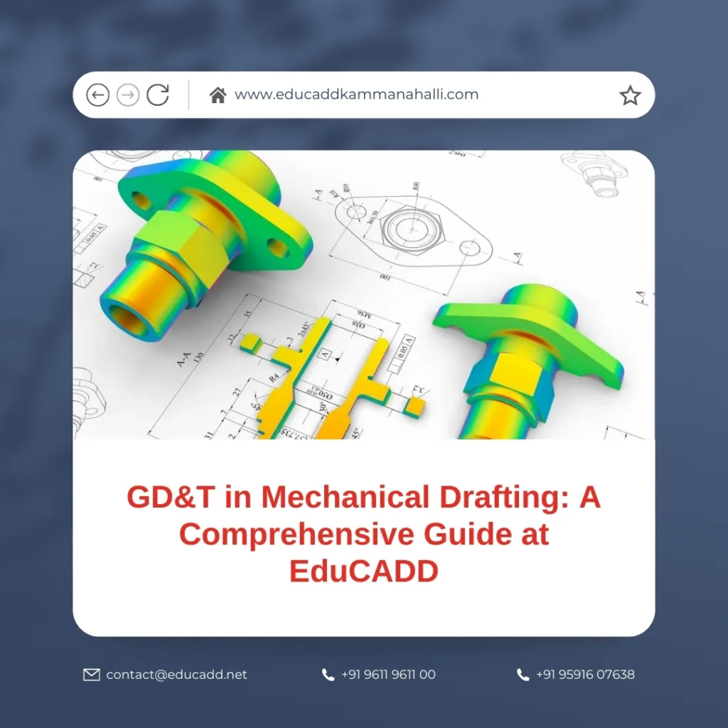
In the modern mechanical design and engineering world, Geometric Dimensioning and Tolerancing (GD&T) plays a vital role. Professionals in mechanical drafting rely on GD&T to ensure precise communication, accurate manufacturing, and smooth quality control. At EduCADD, students gain hands-on experience with GD&T tools, learning how to translate engineering designs into accurate, manufacturable components. This comprehensive guide provides a detailed roadmap for anyone looking to enhance their skills in mechanical drafting using GD&T principles.
Understanding the Fundamentals of GD&T
Geometric Dimensioning and Tolerancing, commonly referred to as GD&T, is a system used in mechanical drafting to describe the size, form, orientation, and location of features on a part. Unlike traditional dimensioning, GD&T provides a standardized way of communicating design intent and manufacturing requirements.
At EduCADD, instructors emphasize clarity in GD&T symbols, ensuring students can interpret and apply standards accurately. GD&T allows engineers to specify allowable variations in part features without sacrificing functionality. This approach minimizes manufacturing errors and reduces rework costs.
For instance, when designing a shaft that fits into a bearing, GD&T can define the precise tolerance limits for diameter, roundness, and alignment. By mastering these basics, drafters can produce drawings that ensure parts fit perfectly in assemblies.
Transition in practice: By first grasping the core principles, students can confidently move to advanced GD&T concepts, such as positional tolerances, profile tolerances, and datum reference frames.
Key GD&T Symbols and Their Applications
GD&T uses a variety of symbols to define relationships between features and the allowable limits of imperfection. Learning these symbols is critical for anyone aiming to excel in mechanical drafting.
1. Form Tolerances
Form tolerances control the shape of a feature. Common symbols include:
-
Flatness – ensures a surface is level within tolerance.
-
Straightness – maintains the linearity of a feature.
-
Circularity – controls roundness for holes or shafts.
-
Cylindricity – combines roundness and straightness for cylindrical features.
Form tolerances are simple yet crucial. At EduCADD, practical exercises help students apply these tolerances to real-world components.
2. Profile Tolerances
Profile tolerances define the contour of surfaces. They include profile of a line and profile of a surface symbols. These tolerances allow designers to specify complex surfaces with precise limits.
For example, a camshaft may require a profile tolerance to ensure smooth motion and correct alignment with other components.
3. Orientation Tolerances
Orientation tolerances control the tilt or slant of features. Examples are:
-
Parallelism – keeps a surface parallel to a datum.
-
Perpendicularity – ensures surfaces meet at right angles.
-
Angularity – specifies an exact angle relative to a datum.
Applying these tolerances correctly prevents assembly misalignment and improves overall product reliability.
4. Location Tolerances
Location tolerances define the exact placement of features. Key symbols include:
-
Position – specifies the exact location of holes or pins.
-
Concentricity – ensures central axes align correctly.
-
Symmetry – keeps features evenly distributed around a datum.
These tolerances are particularly critical in high-precision assemblies, such as aerospace components, where minor deviations can cause performance issues.
5. Runout Tolerances
Runout tolerances control how features rotate around a central axis. They include circular runout and total runout. These are essential for rotating parts like shafts and gears.
Transition insight: Understanding each symbol’s purpose allows drafters to combine them effectively, ensuring mechanical designs meet functionality and manufacturability requirements.
Practical Applications of GD&T Mechanical Drafting Guide
GD&T is not only a drafting standard; it’s a practical tool used daily in engineering and manufacturing. Mechanical drafters apply GD&T in several ways:
Design Communication
GD&T eliminates ambiguity in technical drawings. Engineers and manufacturers interpret symbols the same way, reducing errors and improving collaboration. For example, a tolerance specification for a bearing seat ensures the bearing fits without requiring multiple iterations.
Quality Control
Inspection teams rely on GD&T to measure and verify part features. Using tools like coordinate measuring machines (CMM), they compare manufactured parts against design specifications, ensuring compliance and reliability.
Cost Reduction
GD&T reduces unnecessary over-specification. Traditional tolerances often lead to tighter, expensive tolerances than needed. GD&T specifies tolerances based on function, allowing cost-effective manufacturing without compromising quality.
Assembly Efficiency
Parts with GD&T-compliant dimensions fit together seamlessly. Reduced misalignment and interference lead to fewer assembly issues, faster production, and lower rejection rates.
Transition point: By applying GD&T principles, drafters create designs that are both precise and practical, improving overall engineering efficiency.
Benefits of Learning GD&T at EduCADD
EduCADD offers a comprehensive learning environment for GD&T in mechanical drafting. Here’s why students prefer EduCADD:
Expert Guidance
Industry professionals lead courses, providing step-by-step instruction and real-world insights. Learners receive personalized feedback, helping them correct mistakes early and build confidence.
Hands-on Projects
Students work on live projects simulating manufacturing scenarios. These exercises reinforce theoretical concepts and ensure practical skills development.
Advanced Software Training
EduCADD integrates CAD tools like AutoCAD, CATIA, SolidWorks, and NX into GD&T training. Students learn to annotate drawings, apply tolerances, and validate designs digitally.
Certification and Placement Support
Completing the GD&T course at EduCADD offers certification recognized by industries. Additionally, placement assistance ensures learners find opportunities aligned with their skills.
Transition strategy: The combination of theory, practice, and placement makes EduCADD an ideal place to grow a career in mechanical drafting with GD&T expertise.
Tips for Effective GD&T Implementation
Learning GD&T is just the first step. Applying it correctly in real-world projects requires skill and attention. Consider these tips:
1. Understand Functional Requirements
Always align GD&T tolerances with part function. Over-specifying can increase costs, while under-specifying may compromise performance.
2. Use Datum References Wisely
Datum features form the basis of GD&T. Select stable, functional, and easy-to-measure features as datums to simplify design and inspection.
3. Keep Drawings Clear
Ensure that drawings are easy to read and understand. Avoid cluttered annotations, and use consistent symbol placement.
4. Validate Designs with Software
Modern CAD tools allow simulation and tolerance analysis. Validate GD&T annotations before production to reduce errors.
5. Stay Updated with Standards
GD&T standards evolve over time (e.g., ASME Y14.5). Regularly update your knowledge to remain industry-relevant.
Transition summary: Following these practices ensures that GD&T is applied efficiently, reducing errors and enhancing part quality.
Conclusion
GD&T in mechanical drafting is indispensable for modern engineering. By learning GD&T at EduCADD, students gain not only theoretical knowledge but also practical expertise in applying these standards effectively. From understanding basic symbols to applying tolerances in complex assemblies, EduCADD provides a complete roadmap to success.
Investing time in GD&T training enhances career opportunities in mechanical design, manufacturing, and quality assurance. With expert guidance, hands-on practice, and industry-relevant tools, learners can confidently produce precise, high-quality mechanical drawings.
Call to action: If you aim to excel in mechanical drafting and want to gain in-demand GD&T skills, EduCADD offers the perfect platform to learn, practice, and advance your career.

